Earth Retention
‘A’ Frame Micropile Structures and Reticulated Micropile Walls
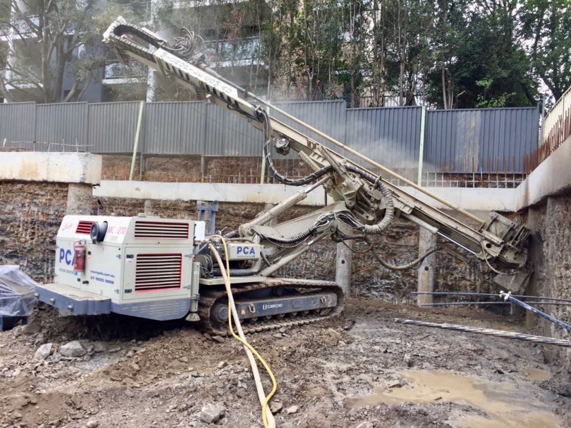
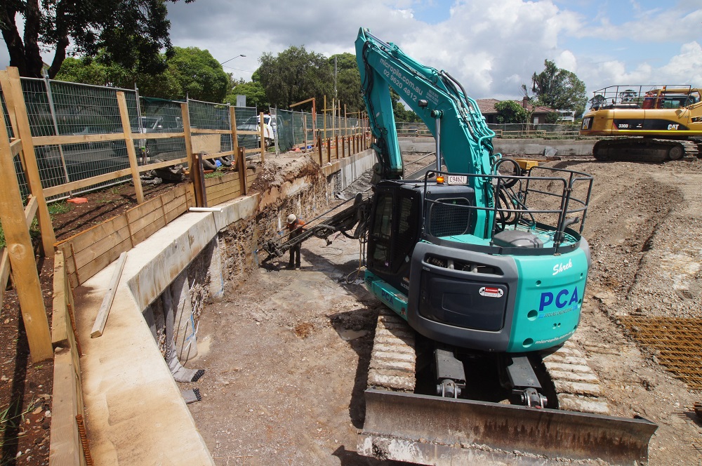
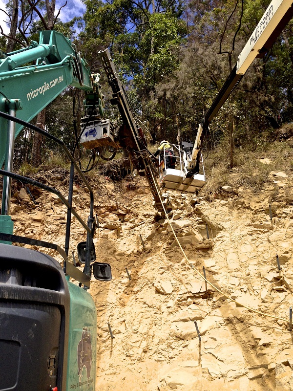
One of the many unique applications for micropiles is where they are utilised together to establish a network of piles referred to as reticulated micropiles.
Reticulated micropiles are typically utilised as components of a reinforced soil mass, which is used for stabilization and support, as examples unstable slopes or in areas where additional capacity needs to be introduced into inadequate soils to support new/existing structures.
When designing, structural loads are applied to the entire reinforced soil mass (surcharge), as opposed to individual pile loads. Micropiles can do this in a cost effective method compared to other pile types because the installation machinery generally has far more flexibility than conventional piling rigs; in addition, micropiles utilised in this application are lightly reinforced, the reduction in reinforcement is possible because individual micropiles are not loaded in isolation.
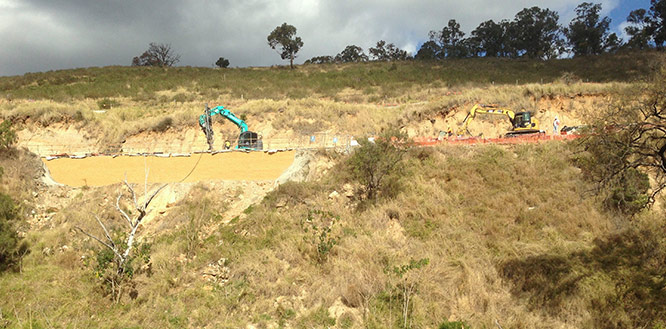
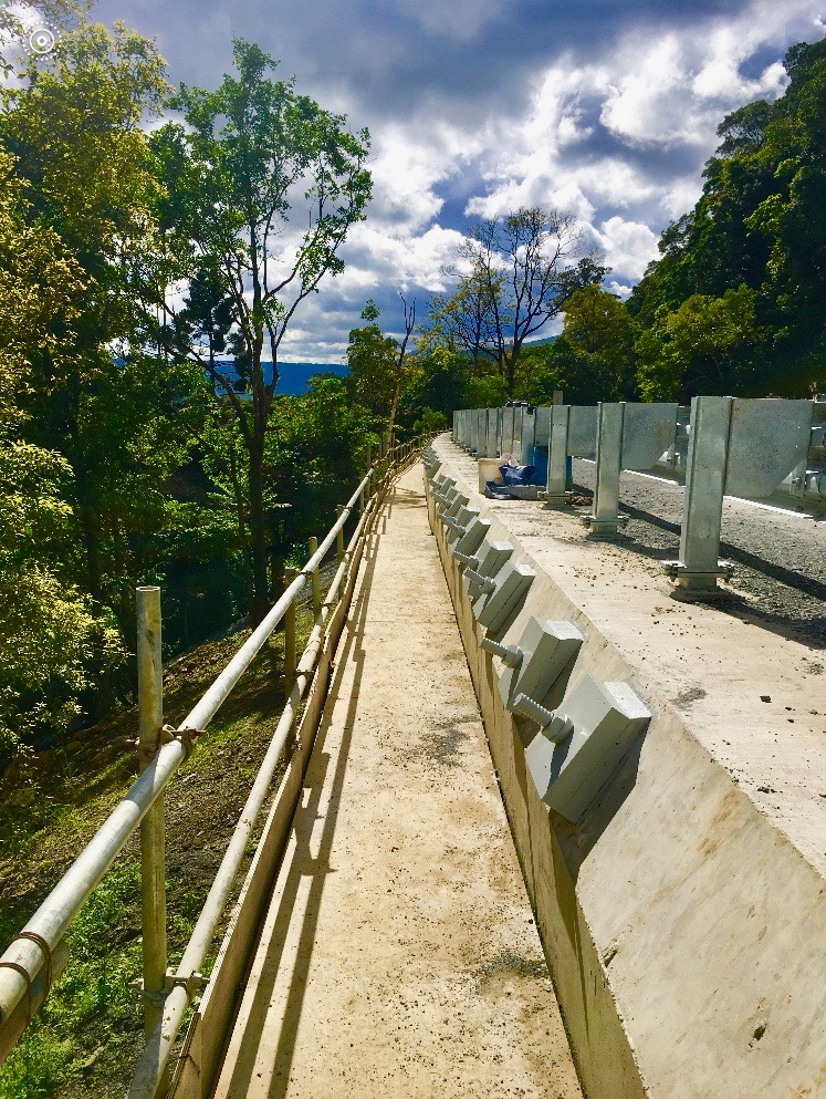
Multiple piles serve to encircle the entire soil mass and ground improve the site “in a network” which then internally strengthens the reinforced soil as a mass or composite. A more commonly utilized version of reticulated micropile structure is referred to as the “A frame” micropile wall, the name linked to the layout of the micropiles which when viewed in section are installed in an “A” type configuration.
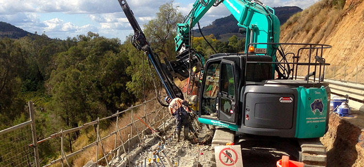
The triangular soil wedge within the “A Frame” acts as a reinforced soil mass while the applied structural and geotechnical loads are carried axially within the piles. This system is often utilised in areas where the slip plane has a factor of safety around 1.00. The piles are generally installed into the underlying bedrock beneath the critical slip failure. The installation of an A frame micropile solution raises the factor of safety against failure from 1.00 pre-construction to 1.5 as a minimum post construction.
Key to the effectiveness of this system is the expertise and equipment that installs and tests and measures the finished piles, PCA has more experience installing “A Frame” micropile structures than any other Australian piling or ground engineering Company.
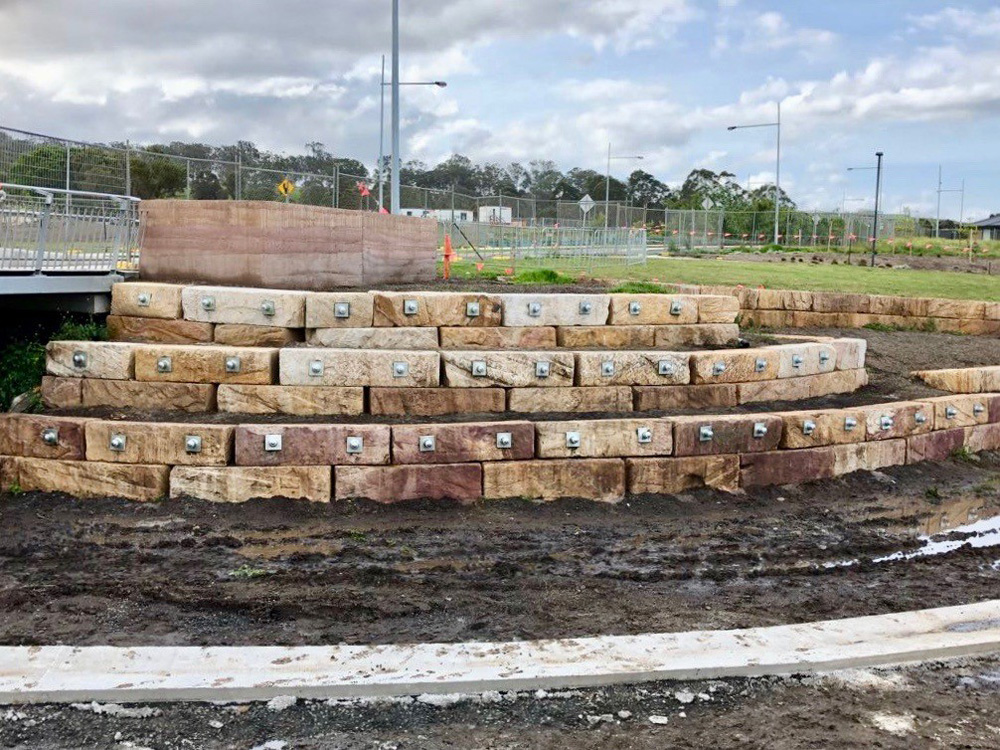
Anchors (Permanent and Temporary)
Anchors are stabilization and support elements that transfer tension loads, using high-strength steel bars or steel strand tendons. A full-length hole is drilled through the soil and into the bond zone in soil or rock using casing if necessary. Threadbar or strand tendon is inserted into the hole and the hole is filled with high-strength grout. Any casing used is then extracted. The length of bar or strand above the bond zone is covered by a bond breaker to eliminate load transfer above the bond zone. The anchor head is then generally tensioned and connected to the structure requiring the support.
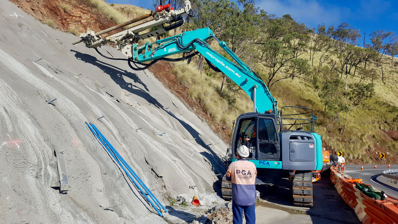
Rock Bolts
Rock bolts are tensioned once the anchorage is attained to actively set up a compressive force into the surrounding rock. This axial force increases the shear capacity and is generated by pre-tensioning of the bolt. The system requires a bond length to enable the bolt to be tensioned. In essence, rock bolts start to support the rock as soon as they are tensioned and the rock does not have time to start to move before the rock bolt becomes effective.
Rock bolts are commonly used throughout the civil engineering mining and tunneling industries. They are used to improve the stability and load bearing characteristics of a rock mass. In the tunneling industry, rock bolts are used for horizontal fore-poling, slope stabilisation at the tunnel portal and for anchoring large section tunnels with high side walls.
Rock Dowels
Rock dowels are very similar to rock bolts, however they are passive reinforcing elements which need some ground displacement to activate the dowel. In installation of rock dowels, a hole is drilled and untensioned steel bars are inserted into the hole. When displacements along joints occur, rock dowels are subject to both shear and tensile stresses. The level and ratio of shear and tensile stress depends on the properties of the surrounding ground, the grout material filling the annular gap between the dowel and the ground and the strength and ductility parameters of the rock dowel itself.
Soil Nails
Soil nailing is an efficient, effective and economical method of earth reinforcement, which allows a controlled improvement of the natural stability of the soil. Soil nails provide friction, shear and tension strength in loose materials, so that when a site is completed it transforms from many independent objects by joining and combining the site all into a new monolithic structure.
Soldier Pile Wall (Board and Beam)
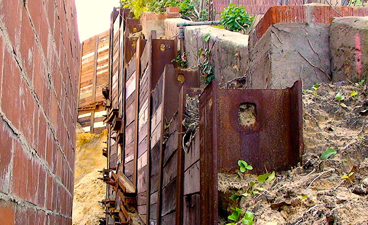
Soldier piles and lagging walls is an earth retention technique used primarily for temporary excavation support. These shoring walls are typically constructed by installing steel beams vertically (soldier piles), which are either driven or drilled at regular intervals around the planned excavation prior to excavation beginning.
The excavation is performed in stages so that the lagging can be installed between the soldier piles resting on the flanges of the steel to retain the soil on the outside of the excavation. There are different products that can be utilized for lagging, steel, precast concrete and wood, which is the most regularly utilised.
The lagging effectively resists the load of the retained soil and transfers it to the piles. Board and beam retaining walls can be designed as cantilever walls, alternatively earth anchors or bracing can be utilized to provide additional lateral support.
Lagging walls are among the least expensive retention systems. Soldier piles can be installed quickly and lagging walls are fast to construct. This technique is versatile and allows for adjustments on site as required.
Earth Retention Design and Construct
Sheet Piling
 Sheet piling refers to an earth retention system that is installed into the ground by driving or pushing, rather than pouring or injecting, sheet piling is generally a thin cross-section material of low weight so that the weight of the wall does not assist in the walls stability.
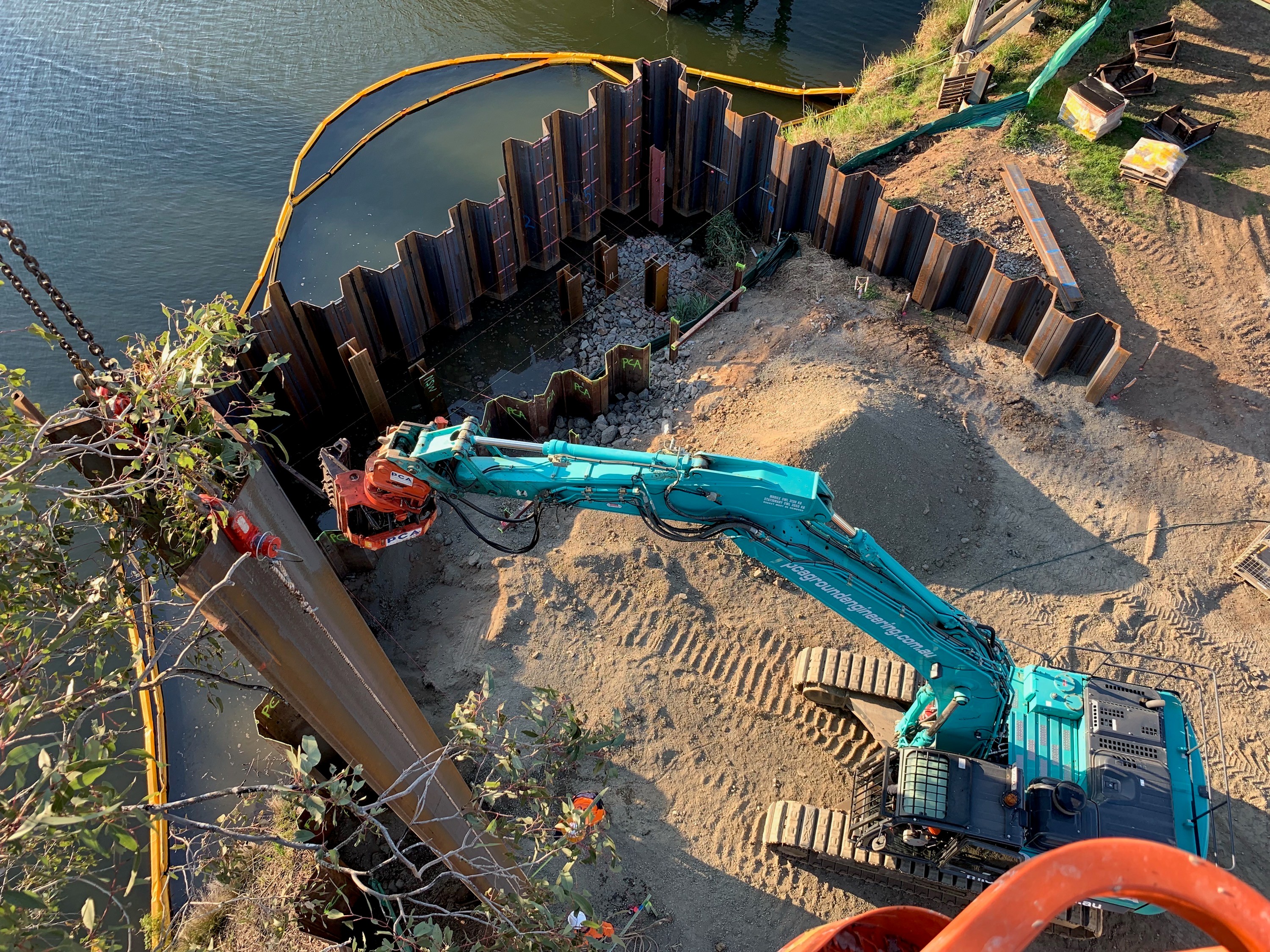
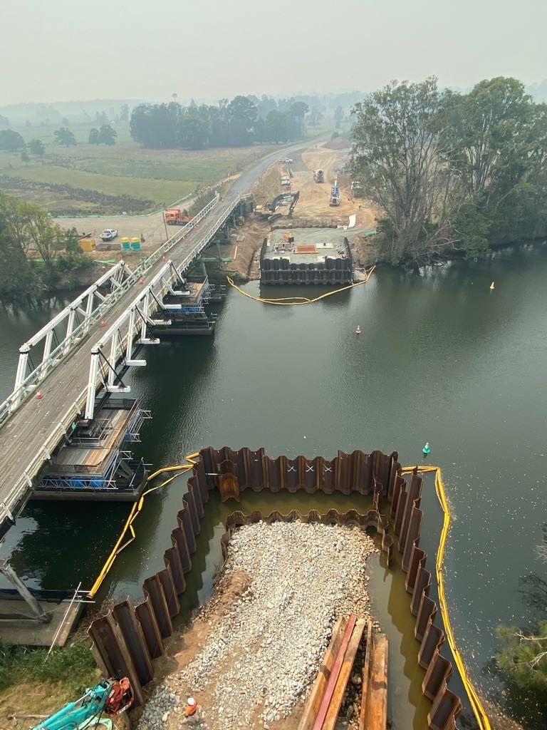
Sheet piling is one of the most regularly utilised earth retention techniques, sheet piles are installed sequentially alongside each other to resist lateral pressure from earth or water. There is a wide range of sheet piling products on the market however the most commonly utilised are steel sheet piles.
Steel sheet piles are thin interlocking plate of steel used to construct a continuous barrier in the ground. They typically interconnect via a clutch which locks the individual sheet piles together joining the edge of one pile into the previous pile. It is the joining of all these sheet piles that creates an interlocked structure to a design depth along or around the perimeter of a construction site. The continuously interlocked sheet pile wall forms either a permanent or temporary lateral earth support that can significantly reduce groundwater ingress.
Sheet piles can be installed with impact hammers, hydraulic presses and vibratory hammers. If soils are too hard or dense, pre-drilling or water jetting can be required to complete the installation. Earth anchors can easily be installed through sheet piling to provide additional lateral support for deeper excavations or increased loads.
The installation of sheet piles can create significant vibration to neighbouring structures and accordingly installation risk needs to be a major consideration when utilizing this technique. Sheet piles can provide a long design life with the application of protective coatings, cathodic protection or the substitution of non-corrosive sheet such as concrete, vinyl or fiberglass.
Sheet piling has numerous applications because of its relative speed, cost and re usability of steel sheet piles on numerous projects. The primary application for sheet piles is for temporary retaining walls or cofferdams which are installed to allow the permanent structural solution to be built.
Grout Retaining Walls
Grout retaining walls are created from grouted soil columns utilising high pressure grout techniques, mini jet and jet grouting. These grout columns combine to produce panels which are typically installed to a design specification to create a gravity retaining wall. Grout walls can be created in all geo-technical conditions, however they are specifically suited to sands, silts and clay.
Grout columns or pile diameters typically range form 200mm-1500mm depending on variables such as;
- Design requirement
- Geo-technical conditions
- Machinery capability
- Fluid injection method
Grout walls easily achieve a 3m exposed excavation making them an ideal solution for a single basement level excavation. The exposed face height can be increased with the use of walers, anchors or shoring. Wall height is correlated back to the walls weight, grout column interaction with soil and passive earth pressure of the structure being designed.
Grout walls can be a very cost effective solution and specifically suit sites with adjoining structures such as utilities, masonry walls and fences. There is negligible vibration to create a grout retaining wall in comparison to other earth retention methods, such as sheet piling. Another significant advantage of this technique is that the introduction of the grout improves and protects the earth to be retained, greatly negating the risk associated with settlement of surrounding structures.
Earth Retention Design and Construct
See Grout Shoring Wall Animation
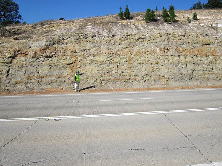
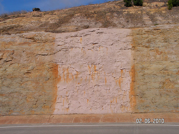
Membranes Cement Latex
PCA can supply and place sprayed support and sealing systems for use in a large range of applications including the mining and civil engineering sectors. Spray on liners can be an effective alternative to shotcreting for unstable batters and slope surfaces, where surface control measures are required (scat control). Spray-on membranes provide a lining to bind loose rocks and earth together and at the same time provide a weather proof membrane.
Benefits of spray on membranes:
- Sealing of the rock surface against weathering
- Not effected by corrosion
- Rock surface support and scat control in development roadways
- Rock surface sealing and support in escape ways and ventilation shafts.
- Water sealing for seasonal water ingress
- Sealing of ventilation devices to improve efficiency
- Longwall face support for roadways
- Lining between shotcrete/concrete layers.
- Safely utilised in underground conditions such as tunnels and mines.